The leading knowledge exchange for Data Center, IT and Mission Critical professionals.

By Munther Salim, Ph.D. C.E.M., LEED AP, CDCEP, ATS

INTRODUCTION
Nowadays, High Performance Computing (HPC) and Artificial Intelligence (AI) solutions are being deployed on premises, in the cloud, or at the edge across a wide range of industries. In manufacturing, HPC and AI are being used for predictive and prescriptive maintenance, automation of product lifecycle management and short design cycles. Additionally, HPC and AI solutions are being used in health care and life sciences to accelerate drug discovery and develop more personalized healthcare. Also, weather and climate research employ these solutions for timely and more precise weather forecasting and improved understanding of climate change. The energy, oil, and gas sector uses these solutions for developing real time wind and solar maps for energy optimization and Better photovoltaic efficiency. HPC and AI transformed the financial services industry through applications across many areas including stocks and securities modeling, fraud detection, credit risk assessment, customer engagement, cyber security, and regulatory compliance. According to a study by Grand View Research, the global HPC market is expected to reach $60 billion by 2025.
Today, IT leaders struggle to adequately power and cool IT equipment in their traditional and colocated air-cooled data centers. Processors are now exceeding 200W, and graphics processing units (GPUs) are operating at over 300W with components continuing to get even more power-hungry. High-density rack configurations in the high-performance computing (HPC) space are moving from 20 kW to 40 kW—with estimates that they will reach beyond 70 kW per rack by 2022. It is not uncommon today to see custom liquid cooled HPC racks consuming 70 to 120 kW. In fact, power densities tend to double every seven years. This technology article first explains the limitations of traditional cooling practices. Then it describes a range of systems you can choose from to modify or supplement
your existing cooling system to get the cooling capacity your data center requires. It also sheds light on power distribution and space trends in accordance with HPC and AI environments.
FROM “LOOSELY” COUPLED TO “NEAR” COUPLED TO “CLOSE” COUPLED TO “DIRECT LIQUID” COOLING
Traditional data centers typically implemented room cooling or loosely coupled cooling. Over the past decade or so, many energy efficiency improvements and air management best practices were implemented in legacy as well as modern data centers such as hot aisle/cold aisle air streams, minimization of air mixing due to bypass and recirculation air, matching supply air to server air flow, maximization of air flow ΔT, elevation of supply air temperature, and employing free cooling technologies using water side and a variety of air side economizers.
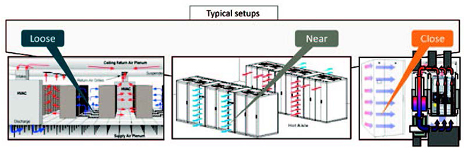
As the density/rack increased beyond 15 kW/rack, the architecture of cooling systems has moved from perimeter cooling CRAHs/CRACs to near coupled solution as such containment and chimney racks became solutions of choice. Further on, closely coupled solutions such as in-row cooling and rear door heat exchanger solutions were implemented in data centers to counter heat rejection densities that approached 30 kW/rack or even higher (Figure 1). Nowadays, as the industry is facing extreme density racks. i.e., HPC and AI racks more than 50 kW/rack, direct to chip liquid cooling is being employed using a Coolant Distribution Unit (CDU) to bring the cooling water in contact with the heat source (GPU, CPU, etc.). This is considered an advanced energy efficient solution for data center cooling and has important implications in many climates where a chiller-less system is sufficient and relies only on cooling towers or dry coolers to cool down the water without using chillers. As the temperature of water increases, the dependence on chillers is reduced and above approximately 30°C water temperature, chillers are no longer required in majority of climates.
NEAR COUPLED COOLING SOLUTIONS
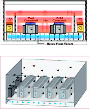
Cold/Hot Aisle Containment
Contained and segregated cold/hot aisles solutions; this results in minimum or no air mixing due to recirculation and bypass. For high density loads there are a number of designs (Figure 2) whose basic intent is to contain and separate the cold air from the heated return air on the data floor: Hot aisle containment; cold aisle containment; contained rack supply, room return; room supply, contained rack return. The separation can be achieved with hard surfaces “glass” or strip curtains. According to HPE data acquired from a large database of assessments, the average data center has a bypass of 50% and an average re-circulation of 40%. Hence, unless hot and cold air streams are physically segregated, good air management can’t be achieved.
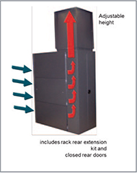
Ducted Cabinet Chimneys—Passive and Active (Fan-Powered)
This solution presents a vertical exhaust duct attached to the top of the cabinet (Figure 3) to provide a sealed pathway for hot air from the top of the cabinet to an overhead drop ceiling as part of a closed hot air return. This solution can be fan-less or with fans to drive air flow and when combined with other thermal management and cooling design best practices can provide from 8 kW to
approximately 30 kW of cooling for fan powered chimneys.
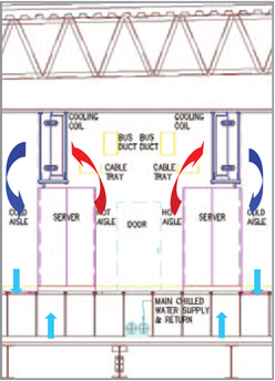
Fan-less Overhead Cooling Coil
Overhead convection cooling places the cooling coils above the racks as shown in Figure 4. This eliminates fans and takes advantage of the IT equipment internal cooling fans to circulate air. This can be used in data centers that are using air cooling. This solution has been installed in data centers also with fans to increase the heat rejection capacity. Both solutions have been used for increased space, cooling, and energy efficiency.
High-density Aluminum perforated raised floor tiles
Another near coupled solution is the high density Aluminum perforated raised floor tiles which directs air toward the equipment achieving a 93% capture index; designed to evenly distribute airflow across the full height of a standard 42U rack, dividing airflow evenly in two directions to provide even distribution to racks on both sides of a cold aisle. This solution has been in adopted in legacy data centers to mitigate thermal issues and hot spots.
CLOSE COUPLED SOLUTIONS
In-Row Cooling
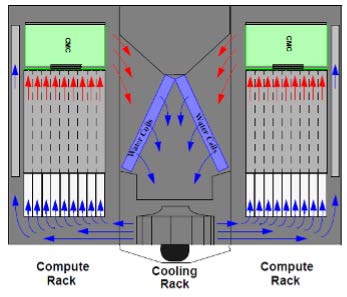
The in-row cooling is a row-based cooling unit moved inside the rows to bring cooling closer to the load supplying cold air directly in front of the racks and can provide up to 30 kW/rack of supplemental cooling. Many manufacturers offer this solution in a variety of densities and can employ a DX cooling unit or chilled water coil. Another near coupled solution that is similar to in-row cooling is the Modular Cooling System shown below which is suitable for high density racks. This solution can provide upward of 40 kW per rack.
CLOSELY COUPLED COOLING SOLUTIONS
Rear Door Heat Exchanger
Close-coupled cooling systems have separate cool air distribution and warm air return paths that are isolated from the open-room air. Closed-loop systems typically use a liquid to air heat exchanger that uses chilled water for removing heat created by IT equipment. Rear door heat exchanger is an example of a close coupled solution which directly removes heat from back of the rack. This solution typically uses chilled water or a pumped refrigerant and CDUs, in-room chillers, or heat exchangers in open loop configuration. Passive rear door heat exchanger units (without fans) are limited to about 15 kW/rack while active units (with fans) are limited to about 45 kW/rack and some sources are saying it can provide up to 70 kW/rack with proper thermal management techniques.
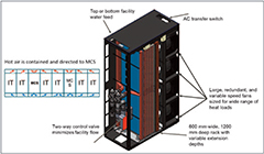
HPE offers a close-couple cooling system, called the HPE Adaptive Rack Cooling System (ARCS). The air flow follows front-to-rear as shown below, but all the ITE air does not require facility input air nor interact with facility return air. In ARCS, the entire heat load is carried by the water, thus no heat load enters the room.
Direct Liquid Cooling (DLC)
Generally, DLC systems are designed specifically for cooling ITE at the component level. They are very efficient and effective for extreme density racks where air cooling falls short. In a typical DLC system layout, Coolant istribution Unit (CDU) is used to transfer the secondary loop heat load (IT) to primary loop (facility water).
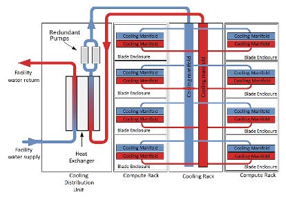
HPE Apollo DLC consists of a cold plate and a tube running coolant over the components within the server, removing the heat from them. A manifold running the length of the rack brings the coolant supply to the servers, with the hot water traveling to a CDU contained within the rack. The CDU then connects to the facility water, up to 32°C (89.6°F), and water return from the servers. aditionally, the liquid-cooled infrastructure has been carefully designed to support multiple processor architectures and accelerator options while remaining forward compatible with next-generation CPU, GPU, and interconnects. This schematic shows the primary loop of the facility water loop and the secondary loop which distributes water to the various cooling manifolds to cool the high wattage components such as CPUs, GPUs, DIMMS, etc.
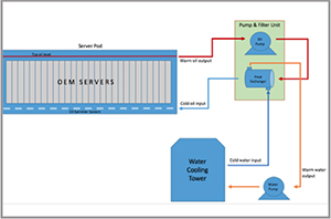
System level Immersion Cooling
One other direct coupled cooling is immersion cooling which can be either a single or two-phase fluid. One particular immersion cooling involves directly immersing compute and network hardware in a non-conductive liquid. Heat generated by the electronic components is directly and efficiently transferred to the fluid, reducing the need for active cooling components, such as interface materials, heat sinks, and fans that are common in air cooling. IT hardware cooled in this manner does not require fans, and the heat exchange between the warm coolant and cool water circuit usually occurs through a heat exchanger, such as a heater core or radiator. The immersion cooling system can provide cooling to extreme densities.
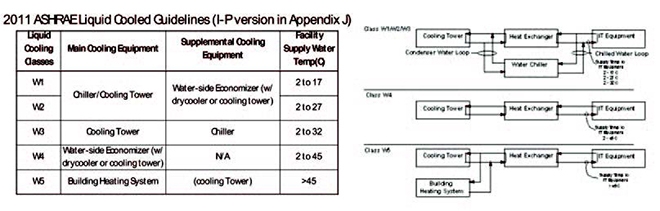
ASHRAE GUIDELINES FOR LIQUID COOLED PROCESSING ENVIRONMENTS
There are five temperature zones into which a DLC system can be categorized based on the liquid cooling temperature directly supporting the IT equipment as shown on Table 1:
CHILLER-LESS COOLING PLANT
So, for direct liquid cooling using warm water, the cooling system topology may look like Figure 9 where chillers are no longer needed in the majority of climates especially if water temperature is at or above 30°C. At 27°C, chillers may be needed for just a few hours out of the year! This is typically achieved by using water side economizer, also known as plate and frame heat exchanger. Chiller-less plants tremendously reduce both the capital expenses and operational expenses of data centers.
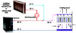
WASTE HEAT RECOVERY
When talking about HPC, waste heat recovery (Figure 10) from return cooling water becomes an opportunity to save energy and improve data center PUE. In many cases, the return water temperatures from HPC racks may exceed 35°C. This water can be used to supplement building heating systems and offset some of the energy that building boilers may produce to meet the heating demand from offices, kitchens, and other domestic use.
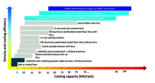
LIMITS AND SELECTION OF PROPER COOLING SOLUTION
Figure 11 shows the limits of types of cooling systems and how it compared to the rack density. Traditional raised floor with perimeter type cooling may be able to cool an average of 10 kW/rack or a little higher. Once the rack density increases beyond 15 kW/rack or so, then near couple solutions will be required. Rack densities up to 50 kW/rack will require close-coupled cooling solutions. Once that limit is crossed, direct liquid cooling or immersion cooling is needed to remove that much heat from servers.
POWER DISTRIBUTION & POWER QUALITY FOR HPC/AI DATA CENTERS
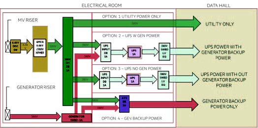
Typical HPC power distribution includes high efficiency utility transformers, ultra-high-efficiency, modular and reliable UPS system for specific workloads. Typically, only the most critical or core workloads such as storage and core systems are backed up by UPS and generators. Depending on the HPC industry and application, HPC workloads can be on utility power only which makes the power distribution much more efficient than enterprise data centers where all IT loads are considered mission critical and are on multiple UPS systems and backed by generators.
USE OF UPS/STANDBY GENERATORS
According to an internal study conducted by HPE, the data gathered from various HPC/AI data centers suggests that the use of UPS depends on business needs or criticality of service and thus varies. However, there are several observations from existing HPC data centers:
POWER QUALITY ISSUES
Classically, all conventional data centers use some form of UPS to protect the mission critical equipment from power quality issues. For example, in certain parts of India, with very poor voltage
regulations, the UPS bypass circuit is customarily disabled so as to not have the load subjected to the unconditioned power of the utility. Modern day HPC data centers have only the critical or core systems protected on UPS. Typically 80% or more of the HPC loads are fed from utility power. Thus, power quality of the electrical system which typically should not be an issue, should be carefully investigated.
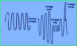
Power quality issues come in two areas:
POWER QUALITY SUPPLY ANALYSIS
The power quality analysis is limited to the sags in the system as it is assumed that the spikes and swells will be mitigated by various electrical devices such as MOVs, SPD’s, filters, etc.
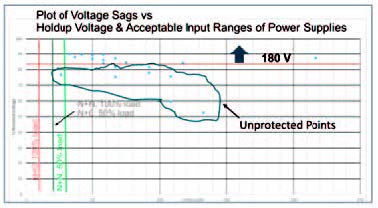
The holdup time and the voltage regulation of the power supply are two parameters which will protect the IT load from minor sag excursions. The graph shows a plot of voltage sags versus hold up voltage along with acceptable input ranges of a typical power supply. Several solutions exist to address power quality supply issues and are beyond the topic to be discussed here.
SPACE AND EXPANDABILITY
HPC data center overall arrangement and architecture have evolved to accommodate the changes in cooling systems and IT equipment and to find economic solutions. HPC data centers have changed from a raised floor with and without galleries to no raised floor and back to a higher “raised floor” of 3-5 m.
The conventional single deck with the raised floor was adequate for perimeter air cooling or loosely coupled cooling. The galleries on the side provided segregation between maintenance and crafts and the IT personnel and security. As rack power density grew, the raised floor also grew in height. With the employment of close coupled cooling or in-row coolers, rear door cooling systems, and flooded room techniques, the raised floor disappeared to save money and to accommodate larger and heavier racks. With the advent of DLC and piping for cooling systems in the data center, a raised floor and even trenches re-emerged on the scene. This situation opened the case for a double deck. There is even a case where a service provider wanted the flexibility to morph from an HPC to a lower density enterprise style of data center.
There is no one right answer and the choice between a single deck and double deck construction and will be the choice of the user. Here is a synopsis of the considerations for each option:
Single deck design
Double deck design
Munther Salim, Ph.D. C.E.M., LEED AP, CDCEP, ATS is Distinguished Technologist/Director—Data Center Technologies at Hewlett Packard Enterprise. He can be reached at [email protected]